
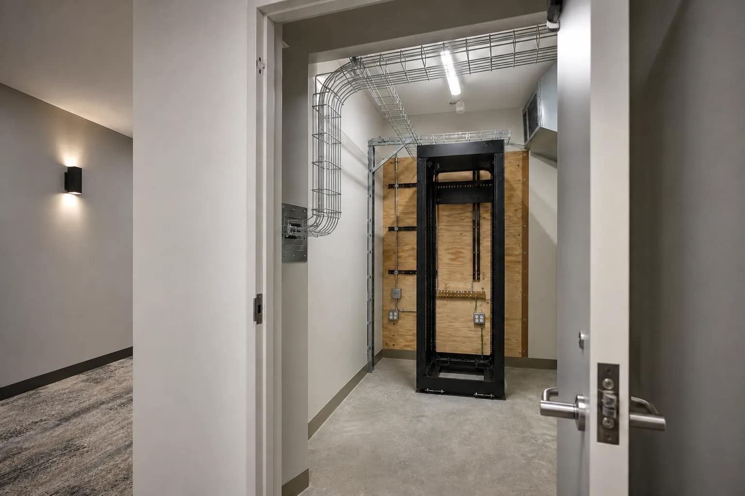
Quick answer: A hotel MDF or IDF should be released for cabling only after the current plans, continuous pathways, penetrations, room finishes, racks and backing, power and grounding, environmental conditions, access, and acceptance evidence have been verified. A room name on a drawing is not proof that a cable crew can complete the work.
The responsibility matrix answers who owns each handoff. The readiness walk answers a different question: is the physical condition actually ready today?
That distinction matters on hotel projects. The electrician may own conduit and power. The low-voltage contractor may own cable, terminations, and testing. A technology vendor may provide electronics. The general contractor may control access, ceilings, and room turnover. When one prerequisite is incomplete, a crew can arrive on schedule and still be unable to pull, terminate, protect, or test the cable.
Release the route, not just the room. Cabling is ready to start only when the complete path from each endpoint to its assigned rack is usable and documented.
Use this ten-point checklist before releasing a hotel MDF, IDF, riser, or floor area for low-voltage installation.
1. Confirm the controlling plans and field conditions
Start with the exact drawing revision that controls the work. Confirm architectural room names, electrical and technology sheets, reflected-ceiling plans, equipment schedules, rack elevations, and approved vendor requirements. Mark which documents are issued for construction and which remain preliminary.
Then compare those documents with the site. Renovations often have undocumented pathways, abandoned cable, moved walls, or telecom rooms that differ from the available plans. New builds can also drift when field coordination changes after the technology sheets were issued.
Release evidence: one dated plan set or field markup showing the approved MDF/IDF, endpoint, and route assumptions.
2. Walk every pathway from endpoint to rack
Do not inspect only the telecom room. Follow representative routes from guest rooms, corridors, public spaces, back-of-house areas, exterior devices, and the service entrance to their assigned rack.
Check conduit, sleeves, tray, J-hooks, pull boxes, handholes, stub-ups, and pull strings. Confirm that routes are continuous, accessible, supported, free of sharp edges, and sized for the project cable count plus the reserve required by the design. Look for blocked sleeves, excessive bends, missing bushings, crushed pathway, standing water, and conflicts with ductwork, piping, lighting, or other trades.
CommScope describes pathways and cable management as part of protecting cabling, maintaining separation, supporting airflow, and preserving room for growth. Its cable-management fundamentals also emphasize planning routes, maintaining bend radius, separating power and data, and leaving serviceable slack.
Release evidence: a route checklist or photo set that identifies every open pathway item by floor, room, and responsible party.
3. Resolve penetrations and firestopping before concealment
Identify every wall and floor penetration the cable route requires. Confirm who creates the opening, who installs sleeves, who provides the listed firestop system, who seals temporary openings during construction, and who restores the final rated assembly.
The low-voltage crew should not discover after ceilings close that a required sleeve is missing or that a route cannot cross a rated wall. The project team should also avoid treating unapproved foam or an unlabeled field patch as accepted firestopping.
Requirements vary by assembly, jurisdiction, project documents, and the authority having jurisdiction. Use the approved design and listed system for the actual condition.
Release evidence: approved penetration locations, a named firestopping owner, and a closeout method tied to the project requirements.
4. Make the MDF or IDF a finished, controlled work area
A telecom room should be clean enough to receive cable and equipment without exposing them to active sanding, painting, leaks, or construction debris. Confirm that walls and floors are complete to the required stage, the room is weather-tight, temporary storage has been removed, and unrelated trades are not using the space as a general closet.
Verify the permanent door, lock, lighting, ceiling condition, and safe access route. The room should remain available throughout installation rather than being repeatedly blocked by stored materials or unfinished work.
Release evidence: dated room photos and an access plan naming who can admit crews during normal and after-hours work.
5. Verify racks, backboards, and cable management in their final positions
Confirm the rack or cabinet location against the approved elevation and clearances. Check wall backing, anchoring, ladder rack or tray, vertical and horizontal cable management, patch-panel space, equipment depth, door swing, and the route by which cable enters the room.
A rack installed a few feet from its planned position can change cable lengths, pathway transitions, equipment clearances, and power locations. A backboard that is missing, painted incorrectly for the project requirement, or covered by another trade can delay wall-mounted hardware.
Siemon’s telecommunications design guidance treats room construction, rack elevations, pathways, power, heat loads, bonding, grounding, firestopping, and MEP requirements as coordinated parts of one design package.
Release evidence: a room elevation or marked photo confirming the installed positions and reserved space.
6. Confirm power, grounding, and bonding
Match receptacle quantities, circuit requirements, UPS plans, and equipment locations to the actual rack and vendor load. Confirm that dedicated power is installed, labeled, energized when required, and available without temporary extension cords.
Verify the telecommunications grounding and bonding infrastructure specified for the project. Assign who installs the busbar or approved connection point, who bonds racks and pathways, and who inspects or tests the completed work. Do not assume that a nearby electrical panel or metal conduit automatically closes the telecommunications bonding scope.
Release evidence: labeled circuits, approved grounding/bonding points, and the responsible electrician’s or engineer’s acceptance record where required.
7. Check cooling, airflow, moisture, and construction risk
Telecommunications electronics need the environmental conditions defined by the project and equipment manufacturers. Confirm permanent or approved temporary cooling, airflow around cabinets, thermostat and sensor locations, and a clear path for heat to leave the room.
Look above and around the room for roof leaks, condensate lines, plumbing, sprinkler work, dust-producing activity, and any condition that could damage cable or electronics. Confirm whether active equipment can be installed now or whether the room is ready only for passive cabling.
CommScope’s structured-cabling overview notes that IT rooms need suitable space, security, lighting, HVAC, and growth capacity. Those are release conditions, not details to discover at turnover.
Release evidence: a room-condition record that separately states readiness for cable, termination, and active electronics.
8. Release the service entrance and backbone route
The MDF may be ready while the route from the carrier demarcation, property entrance, another building, or an upper-floor IDF is not. Verify service-entrance conduit, handholes, pull boxes, riser sleeves, backbone tray, fiber enclosures, and access to every intermediate space.
Coordinate provider survey requirements and lead times separately from inside-plant cabling. Record where the provider’s responsibility ends and where the hotel’s pathway, power, grounding, rack, and patching responsibilities begin.
Release evidence: an end-to-end backbone route markup and a separate carrier/demarcation action list.
9. Confirm endpoint rough-in and finished-location coordination
Before pulling horizontal cable, verify the final location and support condition for Wi-Fi access points, cameras, displays, phones, guestroom media panels, point-of-sale devices, access-control components, A/V endpoints, panic buttons, and other connected systems.
Check boxes, backing, ceiling type, device brackets, furniture and millwork, door swings, mirrors, artwork, sprinklers, lights, and required viewing or coverage areas. Specialty vendors should approve the cable type and endpoint requirement before the cable is concealed.
Release evidence: approved locations and cable requirements tied to the same labels that will appear in testing and closeout.
10. Hold a documented release walk
Finish with a joint walk involving the parties who own construction, electrical, low-voltage, and technology dependencies. Record each open item with its location, owner, due date, effect on the work, and photo. Separate true blockers from items that can be completed safely in parallel.
Use a clear release status for each area:
- Released: the complete route and room are ready for the planned activity.
- Released with conditions: named minor items can proceed in parallel without risking rework or cable damage.
- Not released: a pathway, room, safety, access, power, environmental, or design condition prevents the planned work.
Do not convert an unresolved blocker into an installer assumption. If the team changes the route or endpoint, update the controlling markup and responsibility record before work proceeds.
Release evidence: a signed or acknowledged readiness log, current photos, and one owner for every remaining condition.
The five-minute owner check
Before approving mobilization, ask:
- Can the crew trace a usable route from each approved endpoint to the correct rack?
- Are racks, backing, power, grounding, cooling, lighting, security, and access ready for the planned phase?
- Are penetrations, supports, and firestopping assigned and coordinated with concealment dates?
- Do the plans, take-off, vendor requirements, labels, and field conditions describe the same scope?
- Does every open condition have a named owner, due date, and visible effect on the schedule?
If any answer is unclear, the project is not ready for an unconditional release.
This readiness checklist works best beside a hotel low-voltage responsibility matrix. One defines ownership; the other proves the work area can be turned over without avoidable remobilization, damage, or rework.
JET Hotel Solutions helps hotel owners coordinate drawings, take-offs, pathways, low-voltage installation, specialty vendors, carrier dependencies, testing, and closeout across new builds and renovations. Explore JET’s hotel low-voltage services and project delivery process.