
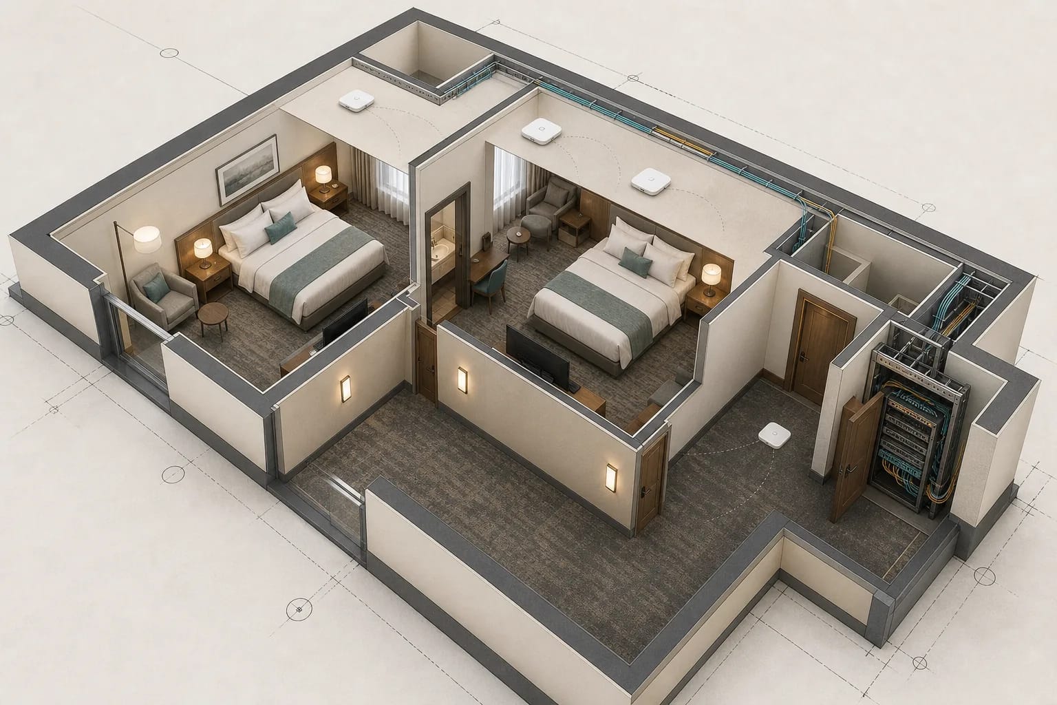
A hotel Wi-Fi access-point schedule can total correctly and still describe the wrong hotel.
The room count may come from an older drawing set. A corridor access point may have been carried forward after the design moved coverage into guestrooms. Public areas may appear on the floor plan but not in the equipment schedule. The access points may be shown, while the switch ports, power, cabling, and closet capacity required to support them remain unresolved.
That is why Wi-Fi approval should not be a quick check of the final access-point quantity. Owners, developers, operators, IT teams, and low-voltage partners need one reconciled record that connects the current room program, floor plans, access-point types, locations, infrastructure, survey assumptions, and decision ownership.
Do not approve an access-point total until the room count, placement map, equipment schedule, and supporting infrastructure all describe the same hotel.
1. Lock the current plan set and room count
Start by naming the architectural set that controls the review. Record its date and revision, then confirm the current key count, room types, accessible rooms, suites, connecting rooms, staff areas, meeting rooms, food-and-beverage areas, outdoor spaces, and back-of-house zones.
This sounds basic, but room counts often move while technology proposals are still being developed. A floor can be reconfigured, a suite can become two keys, or an amenity area can change use. If the Wi-Fi schedule was built from an earlier program, the final total may be internally consistent but no longer match the project.
Create a short reconciliation table by floor and area. It should show the current architectural room count, the count used by the Wi-Fi design, and any variance that still needs a decision.
2. Reconcile access points by floor and coverage zone
A single property-wide quantity hides the places where errors occur. Break the access-point schedule into floors and coverage zones:
- Guestrooms and suites.
- Guest corridors and elevator lobbies.
- Meeting and pre-function spaces.
- Lobby, restaurant, bar, fitness, pool, and other amenities.
- Offices, service areas, loading, engineering, and other back-of-house spaces.
- Outdoor arrival, terrace, pool deck, or event areas when included.
For each zone, compare the plan symbols with the equipment schedule. Every symbol should have an equipment type, and every scheduled unit should have a planned location or a clearly labeled spare or contingency purpose.
If totals do not match, do not solve the discrepancy by changing one spreadsheet cell. Trace the variance back to the floor, room, or space where the design diverged.
3. Confirm what each access-point type is meant to do
Hotel Wi-Fi plans may use different equipment for guestrooms, corridors, high-density meeting areas, outdoor spaces, or specialty locations. Those units are not automatically interchangeable.
The approval record should identify the intended role of each type and the mounting condition that supports it. Confirm whether a device is in-room, wall-mounted, ceiling-mounted, weather-rated, concealed, or serving a high-density area. Also confirm whether a guestroom device supports only Wi-Fi or has additional data-port, pass-through, or power requirements that affect cabling and furniture coordination.
This step prevents a clean-looking equipment total from masking a type mismatch. Ten access points assigned to the wrong application are not ten usable access points.
4. Review placement against the final room and interior design
Placement must work with the hotel that will actually be built. Review access-point locations against ceilings, headboards, millwork, televisions, doors, mirrors, closets, rated walls, decorative finishes, and service access.
In guestrooms, confirm the device will not be buried behind fixed furniture or left with an exposed patch cord. In public areas, confirm that architectural features, ceiling heights, operable partitions, kitchens, or dense construction have not been ignored. In corridors, confirm the planned location still aligns with the coverage strategy and the final wall and ceiling conditions.
When plans are incomplete, label the location as an assumption and assign a date for confirmation. An unresolved location should not silently become an installation instruction.
5. Match every access point to cable, power, and closet capacity
Use the broader hotel network infrastructure blueprint to reconcile AP counts with carrier capacity, closet readiness, segmentation, monitoring, and support ownership.
Each access point needs a complete path back to the network. The review should connect the device location to its serving MDF or IDF, cable route, patch-panel position, switch port, power requirement, and available capacity.
Check at least:
- Home-run distance and pathway feasibility.
- Cable category and any brand or design requirement.
- Switch-port quantity, speed, and Power over Ethernet budget.
- Patch-panel, rack, UPS, electrical, cooling, and closet-space capacity.
- Backbone and uplink assumptions between closets.
- Responsibility for sleeves, access, firestopping, labeling, testing, and closeout.
An access-point map without this infrastructure check is only a placement concept. It is not yet an installable design or a complete owner budget.
6. Separate predictive design from field validation
A predictive design uses drawings, materials, dimensions, and stated assumptions to model coverage. A site survey or field validation tests those assumptions against actual conditions. The project team should know which evidence supports the current approval.
For a new build, many final conditions do not exist when the first design is issued. Record the materials and room conditions that the design assumes, then define when validation will occur. For a renovation, current walls, ceilings, guestrooms, closets, existing cable, and operational constraints should be checked before the team treats the design as field-ready.
The plan should also state what happens when validation requires an access point to move, change type, or be added. That decision affects low-voltage work, switch capacity, finishes, schedule, and budget.
7. Check the spaces guests and staff will actually use
Guestroom coverage is central, but it is not the complete hotel experience. Walk the property program and confirm that the Wi-Fi scope includes every area where guests, staff, systems, or operators expect connectivity.
Meeting rooms may need a different capacity assumption than a quiet lobby. Outdoor areas may need weather-rated equipment and additional pathways. Back-of-house teams may need reliable coverage for operations even when those spaces are not visually prominent on a guest-facing plan.
Document intentional exclusions. An area that is out of scope should be visible as a decision, not discovered after opening.
8. Assign approval, exceptions, and change control
Wi-Fi approval touches several scopes. The provider may own the wireless design, while the low-voltage contractor installs the cable, the electrical team supports power, the general contractor provides access and pathways, and the interior or architectural team controls final room conditions.
Name who approves the room count, placement map, equipment schedule, infrastructure, brand requirements, survey result, and field changes. For each exception, record the owner, due date, budget effect, and drawing or schedule that must be updated.
Then require the same approved basis in procurement, installation, testing, and closeout. That keeps a late field adjustment from living in an email while the plan, equipment order, switch schedule, and budget remain unchanged.
The owner-ready AP approval record
A useful approval package does not need to be complicated. It should contain:
- The controlling architectural plan set and current room program.
- An access-point schedule reconciled by floor, zone, quantity, and type.
- A placement map coordinated with final room, ceiling, furniture, and public-area conditions.
- The MDF/IDF, cabling, switch-port, power, pathway, and capacity basis.
- The predictive-design and site-validation assumptions.
- A visible list of exclusions, exceptions, open decisions, and responsible parties.
- A change-control path that updates the plans, budget, equipment order, and closeout record together.
That package gives ownership a defensible approval instead of a quantity-only signoff. It also gives the Wi-Fi provider, low-voltage contractor, construction team, and hotel operations group the same version of the project.
JET Hotel Solutions helps hotel owners and project teams coordinate technology plans, low-voltage takeoffs, site surveys, infrastructure requirements, bid comparisons, vendor responsibilities, budgets, and project delivery. Bring JET into the review before a room-count or placement mismatch becomes a field change.